Self-Reconfigurable Quadruped from Scratch
The goal of this project was to build a self-reconfigurable quadruped capable of switching between walking and rolling modes. I also integrated ROS2 and YOLO to support a computer vision task.
DEMO
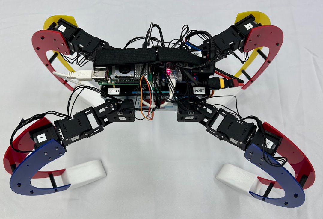
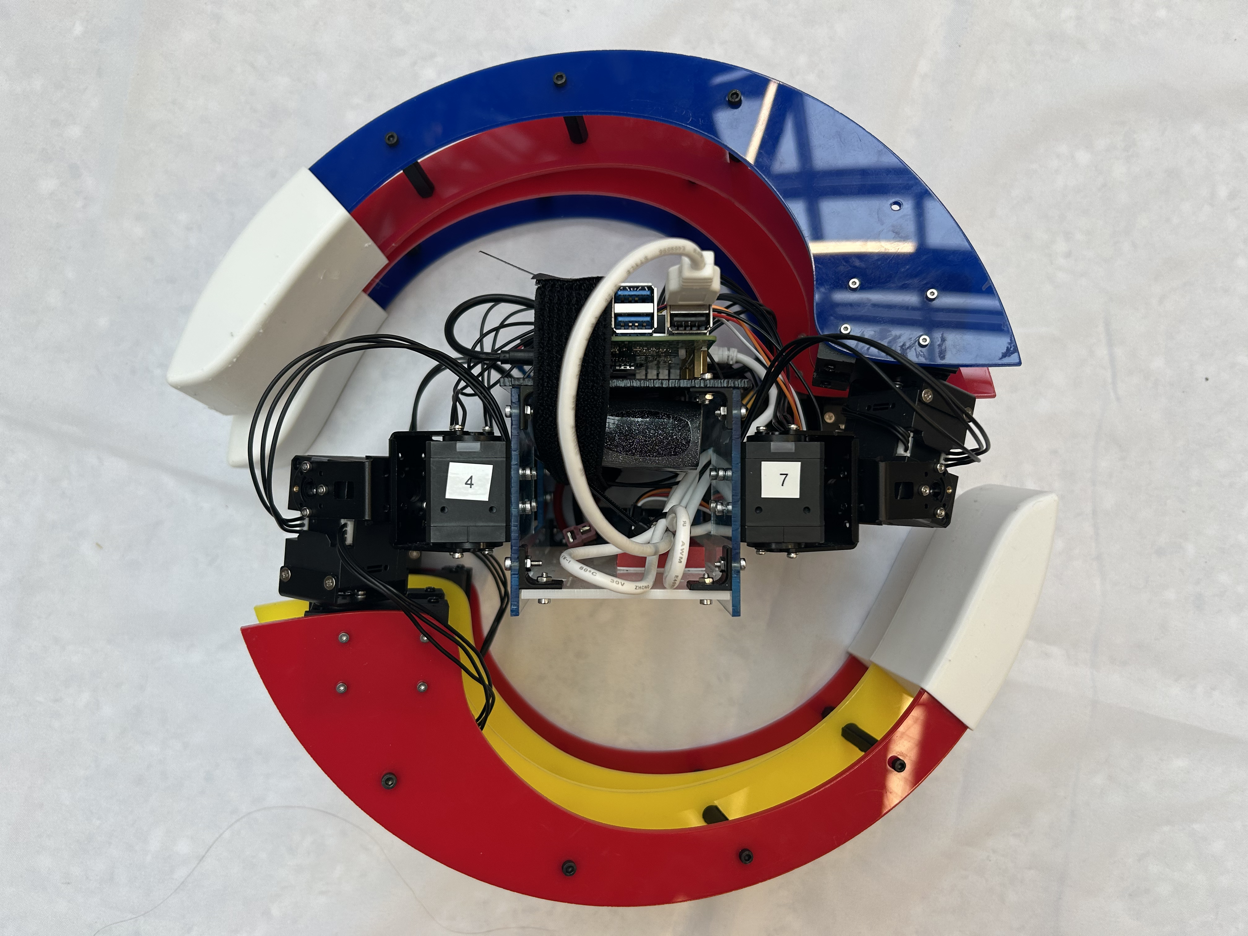
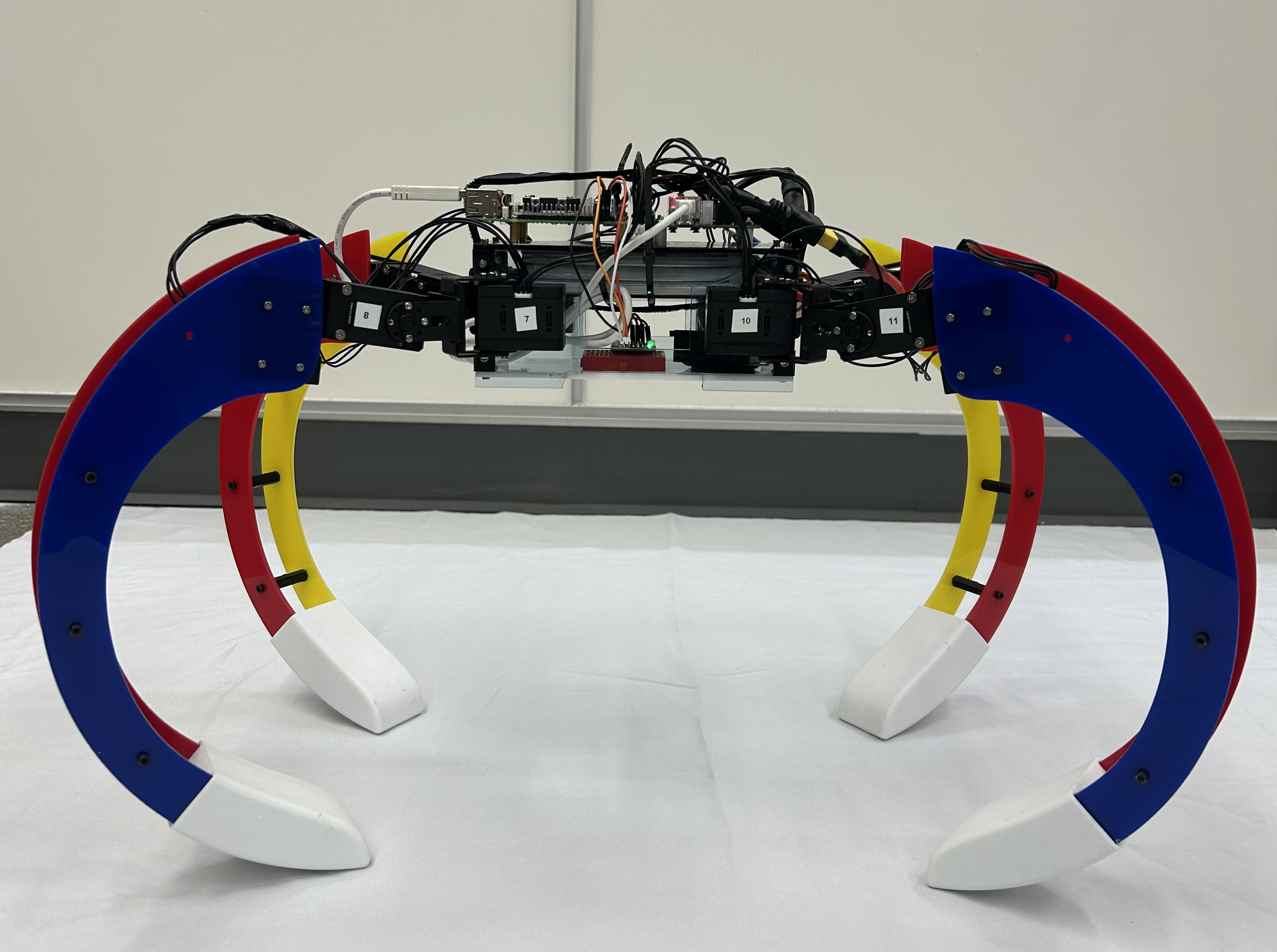
DESIGN
The research paper Scorpio: A biomimetic reconfigurable rolling-crawling robot inspired the design of my robot, which I fully modeled in Onshape.
I chose DYNAMIXEL motors for their high torque output and well-documented ROS2 integration. For the controller, I used the Raspberry Pi 5, which supports Ubuntu and runs ROS2 efficiently.
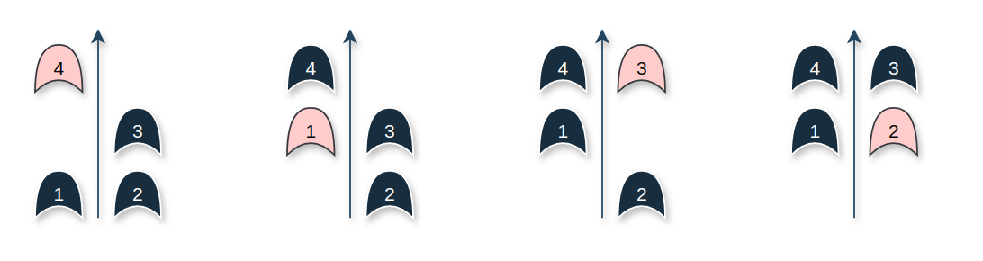
CRAWLING GAIT
Pattern: Move one leg at a time (wave pattern)
Stability: Always 3 legs on ground
Speed: Slow but very stable
Footfall Sequence: Leg 4 → Leg 1 → Leg 3 → Leg 2
Each leg executes:
- Lift: +22° on roll joint
- Swing forward: +10–25° yaw offset
- Lower: returns to home pose
- Body pause: robot rests on all four legs to ensure stability
The gait operates in a real-time control loop that dynamically updates motor positions.
PROCESSING IMU DATA FOR ROLLING
To determine how to propel the quadruped robot in rolling mode, I process accelerometer and gyroscope data from the ISM330DHCX sensor via I²C on a Raspberry Pi 5.
The key goal is to compute the tilt angle of the robot using acceleration in the Y and Z axes:
\[\theta = \arctan\left(\frac{a_y}{a_z}\right)\]where:
- \( a_y \) : linear acceleration along the Y-axis
- \( a_z \) : linear acceleration along the Z-axis
After averaging a short window of tilt measurements, the robot checks if the orientation falls within certain thresholds:
BLUE side under if:
\[\theta_{\text{deg}} \in [-179^\circ, -162^\circ] \cup [167^\circ, 179^\circ]\]YELLOW side under if:
\[\theta_{\text{deg}} \in [0^\circ, 15^\circ] \cup [-23^\circ, 0^\circ]\]Depending on the orientation, the system issues a movement command like to roll forward with YELLOW side propulsion or roll forward with BLUE side propulsion.
The system runs in real time and adjusts its propulsion mode dynamically based on IMU feedback.
COMPUTER VISION AND MACHINE LEARNING
I used YOLOv11 from Ultralytics, trained with a bowling pin dataset to update the number of bowling pins so the robot could transform when it is facing the center of the pins.
AUTONOMOUS BOWLING SEQUENCE
- The robot begins turning while simultaneously scanning for bowling pins.
- There is a 7-second pause between turns.
- If the robot detects at least two pins continuously for 3 seconds, it transitions to rolling mode.
- Once in rolling mode, it reads IMU data to determine tilt angles around the X-axis before rolling forward.
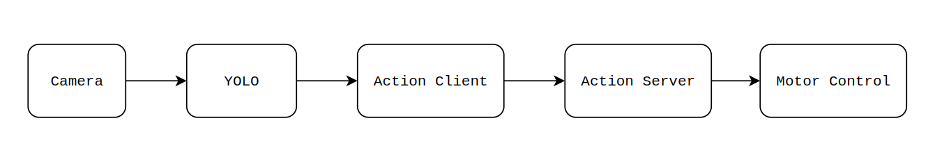
NODES
The bowling task is divided into several subsystems:
Control (Action Server and Client Nodes)
These nodes update the robot’s state (TURNING, STOPPING, TRANSFORM TO ROLLING, ROLLING, etc.) based on the number of detected bowling pins and publish the corresponding robot configuration for the Motor Control Node to set the DXL motors.
Computer Vision (YOLO Node)
This node processes data from the camera and counts the number of bowling pins, publishing the result to a topic.
Dynamixel Motor Control (Quad Motor Control Node)
This node controls the motors based on the robot’s state and processes IMU data to determine tilt angles during ROLLING mode.
HARDWARE
- Raspberry Pi 5
- Intel RealSense Depth Camera D435i
- DYNAMIXEL U2D2 Power Hub
- DYNAMIXEL U2D2
- DYNAMIXEL XC430-T240BB-T Motor (x 12)
- Adafruit ISM330DHCX - 6 DoF IMU - Accelerometer and Gyroscope
- 3S Lipo Battery 5200mAh 50C 11.1V RC Batteries