Color Composer
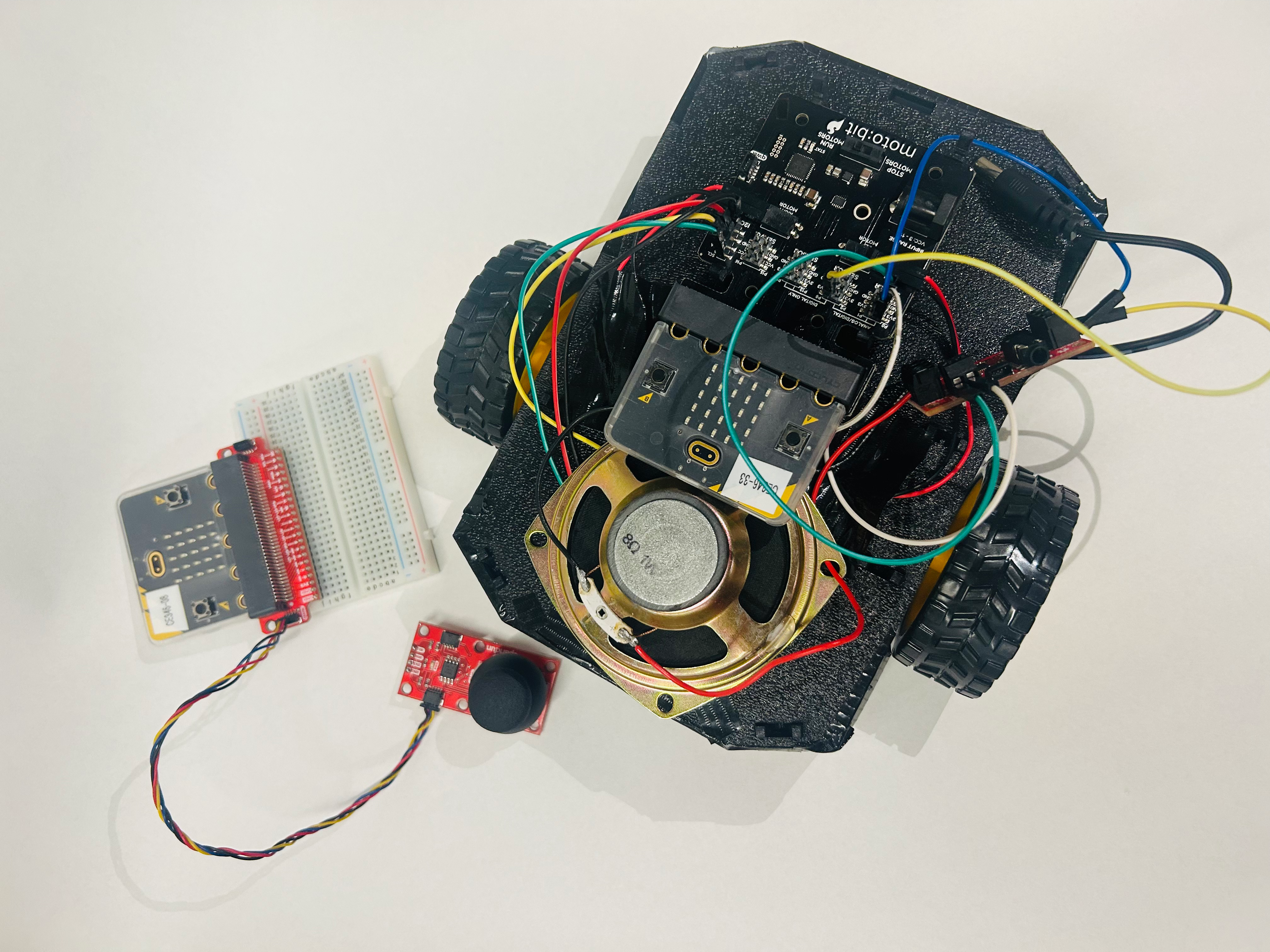
We built a differential drive robot that could be wirelessly controlled via a joystick and two Micro:Bits powered by the nRF52833 microcontrollers. As the robot drives over colors on the ground, it plays music notes that are associated with different colors.
Team Members: Talia Ben-Naim, Natalie Hill
DEMO
APPROACH
Inputs:
- Signal from the joystick
- Color on the ground
Outputs:
- Driving direction
- Music note
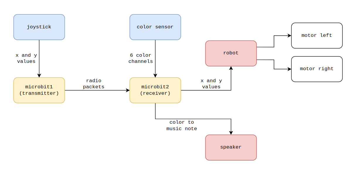
Project flow:
- The user controls the joystick. The x and y directions are encoded in radio packets with a password (“color composer”) and sent from microbit1 (transmitter).
- Microbit2 (receiver) decodes the packets and determines robot direction: forward, backward, forward left, forward right, backward left, or backward right.
At the same time:
- The color sensor reads the ground and outputs six color channels (Violet, Blue, Green, Yellow, Orange, Red).
- These are decoded into a single color (e.g. Violet, Blue, Green, Yellow, Orange, Red, Brown, Black, White).
- The associated frequency is played through the speaker.
COMMUNICATION PROTOCOLS
The joystick (microbit1) and robot (microbit2) communicate wirelessly using the 802.15.4 radio protocol. This allows real-time joystick control.
The joystick, color sensor, and robot motors all use I2C (Inter-Integrated Circuit) for internal communication between components.
MY TASKS
- Process joystick input for wireless transmission
- Implement robot control logic based on decoded joystick commands
HANDLING JOYSTICK INPUT
The joystick communicates with the nRF52833 microcontroller via I2C, using the nRF TWI Manager library to manage transactions. It outputs horizontal and vertical values.
These values are encoded in radio packets as two 16-bit integers (x and y), each split into MSB and LSB. The joystick values are offset from the neutral center and placed in the payload after a password string to avoid interference from other microbits.
Reference: SparkFun Qwiic Joystick Arduino Library
CONTROLLING THE MICROBIT ROBOT
The receiving microbit decodes x and y joystick values by reconstructing the 16-bit integers from the MSB and LSB fields in the packet.
Motor control is handled via the SparkFun moto:bit - micro:bit Carrier Board, which communicates via I2C. The motor_drive function writes speed and direction values to the controller, with helpers like motor_forward and motor_reverse simplifying motion commands.
Reference: Motobit MicroPython Library